R2R DAC Tutorial
R2R network is a network consisting of resistor with values R or 2*R.
They are used for simple fast DACs.
Se more here (wiki)
Pro:
cheap
fast
Con:
for more than 8-9 bit you need very accurate resistors
need additionale buffers at least at output
Simple non-explainded mockup
see here for orginal
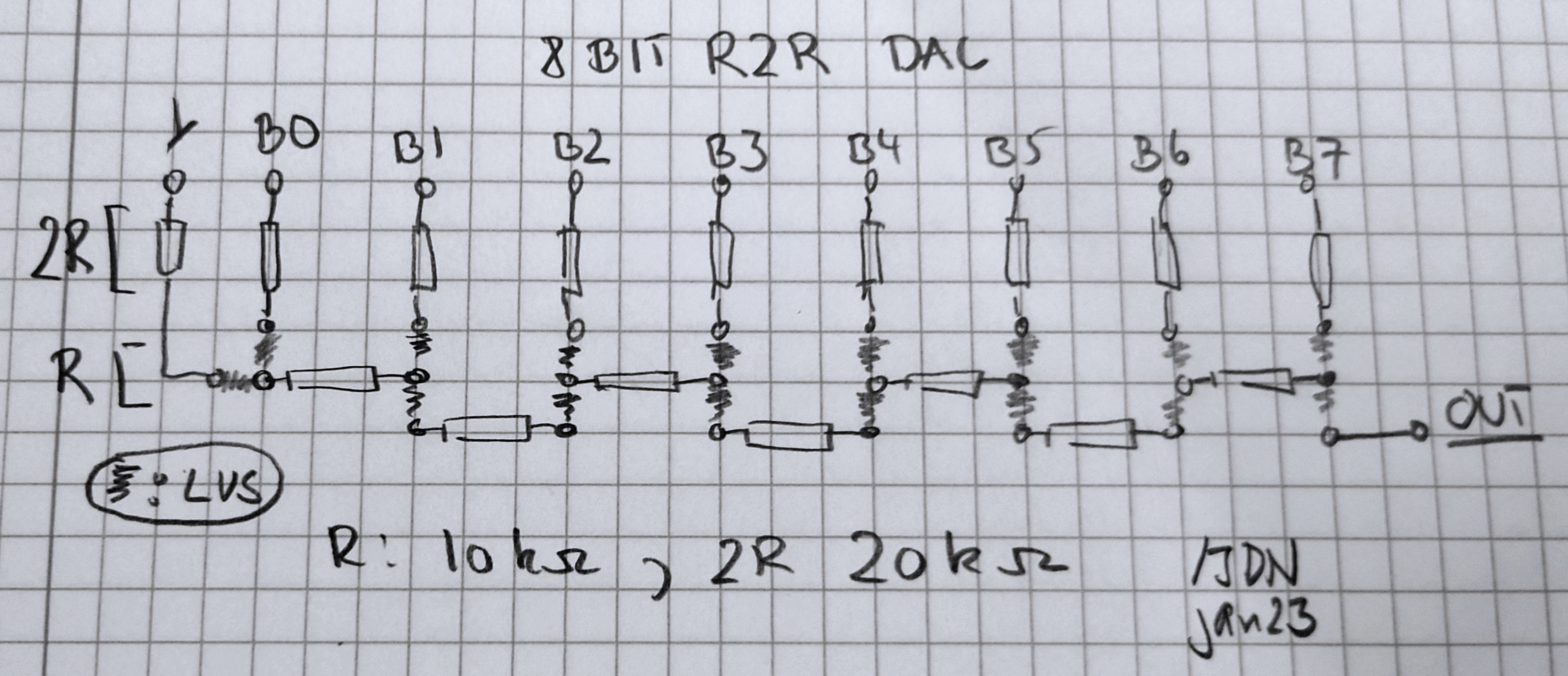
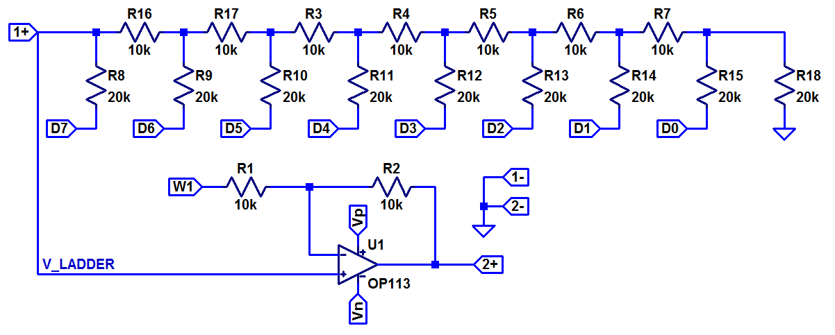
Use 10kOhm (R) and 20kOHm(2R) They will give you a low current load on the digital pins. Many digital pins have a builtin current limitation for one pin AND for the sum of output of digial pins.
Simple vero board mockup for a 8 bit R2R DAC. Use 20kOhm for 2R and 10kOhm for R values /Jens
 |
A little warning
A R2R network has an output impedance of R Ohm. So if you are using R as 10kOhm and 2R as 20kOhm your circuit will have a Thevenin equvivalent output impedance of 10 kOhm.
So the next sage must have this in min and have at least 10-100 times input resistance to avoid voltage loss.
Why ? Because the voltage you will measure is a split between 10kOhm and 1MOhm.
Even this give a reduction to 1M/(1M+10k) = 0.99 or a decrease of 1%….
Or instead a voltage stage you can use a inverting coupling which convert the current to a voltage.
In this case you will have an invering circuit and need symmetric power supply.
See the two proposals below
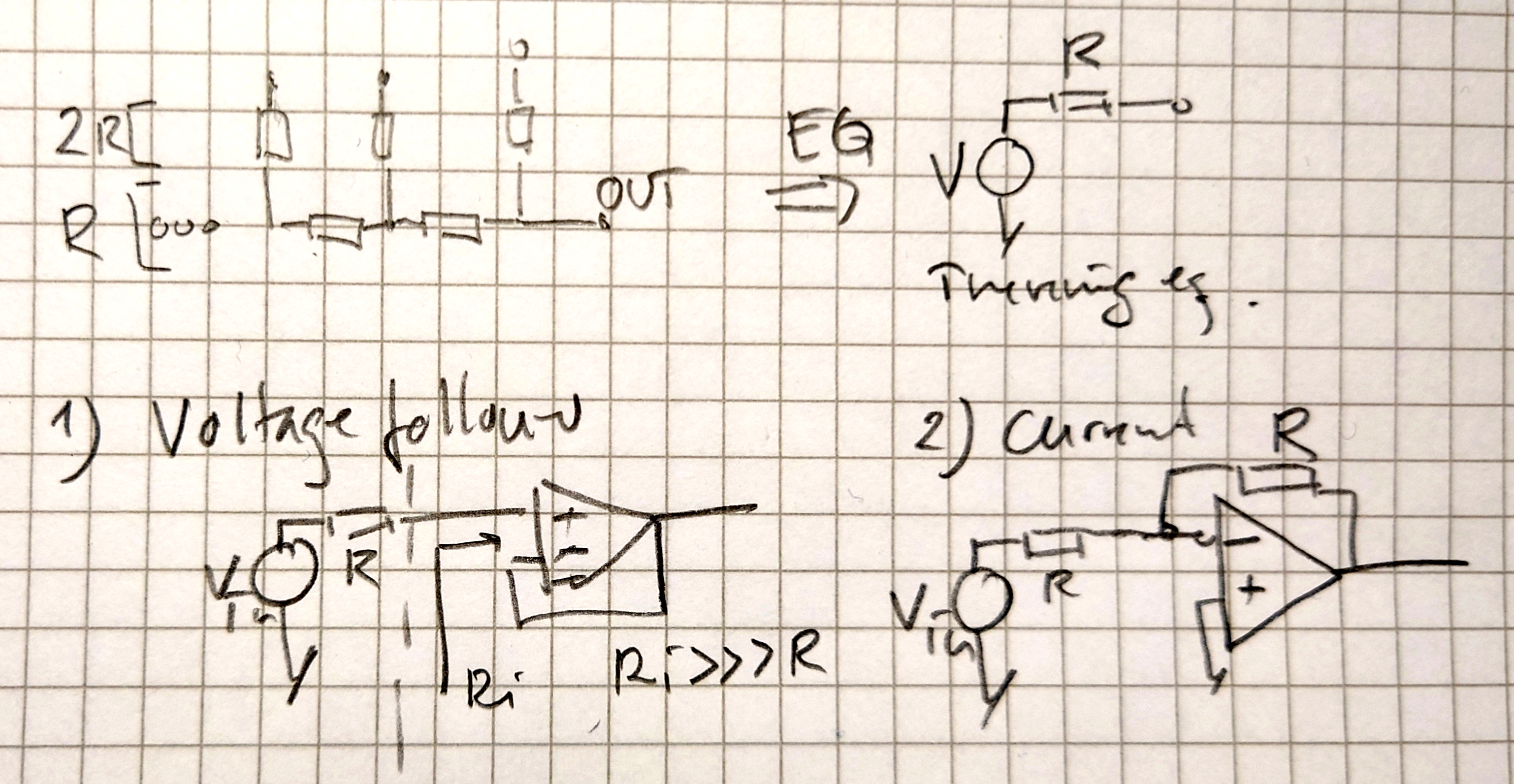 |
Non inv Pro
output [0,Vmax] No need for symm power supply
Non inv Con
Beware of impedance of next stage. If its to low you will loose voltage due to voltage split between Rout of R2R (Ro = R) and Ri of the next stage
Inv Pro
No impedance problem - straight forward
Inv Con
You need a symmetric power for opamp bw its is negative on output. You can change back with another inverting stage but still you need sym power
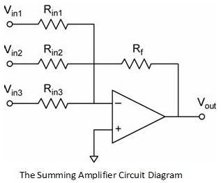
You can go +- on output with a stage adding an offset. Not focus on this small note. Hint add Vmax/2 on Vminus on inv opamp through a resistor value R
Link to summation amps circuits
 |
The math behind R2R
In the following is very nice introduction written by Allan Wolke. All credit goes to him.
In the bottom of this page is some quick adn dirty implementation hints
You can download this page as pdf here
Jens
DAC by use of R2R network
original by Allan Wolke June 23 2015 at https://www.tek.com/en/blog/tutorial-digital-analog-conversion-r-2r-dac
With the recent announcement of the world’s fastest Digital to Analog Converter (DAC) from Tektronix Component Solutions,
I thought it would be interesting to take a quick tutorial tour through one of the simplest DAC architectures – the R-2R resistor ladder network as shown in Figure 1 below.
 |
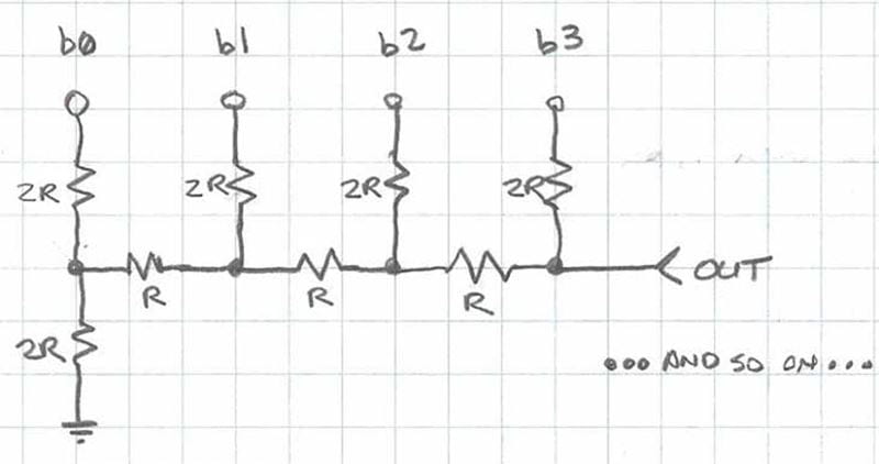 |
Figure 1: A 4-bit R-2R Network
The R-2R resistor ladder network directly converts a parallel digital symbol/word into an analog voltage.
Each digital input (b0, b1, etc.) adds its own weighted contribution to the analog output.
This network has some unique and interesting properties.
Easily scalable to any desired number of bits
Uses only two values of resistors which make for easy and accurate fabrication and integration
Output impedance is equal to R, regardless of the number of bits, simplifying filtering and further analog signal processing circuit designhttps:en.wikipedia.orgwikiResistor_ladder
How to Analyze the R-2R Network
Analyzing the R-2R network brings back memories of the seemingly infinite variety of networks that you’re asked to solve
during your undergraduate electrical engineering studies.
The reality though, is that the analysis of this network and how it works is quite simple.
By methodical application of Thevenin Equivalent circuits and Superposition, we can easily show how the R-2R circuit works.
Let’s start off by analyzing the output impedance. Working through the circuit, simplifying it with Thevenin equivalents, makes this process simple.
Thevenin says that if your circuit contains linear elements like voltage sources, current sources and resistors, that you can cut your circuit at any point and replace everything on one side of the cut
with a voltage source and a single series resistor.
The voltage source is the open-circuit voltage at the cut point, and the series resistor is the equivalent open circuit resistance with all voltage sources shorted.
Figure 2 below shows the locations of the “cut lines” we’ll use to simplify this circuit to calculate its output impedance. For this analysis, the digital inputs will all be considered shorted to ground.
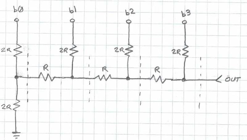 |
Figure 2: Establishing the cut lines for Thevenin Analysis
The two 2R resistors to the left of the first cut line in Figure 2 appear in parallel (when the digital bit b0 is grounded), and can be replaced with a single resistor R as shown in Figure 3. The series combination of the two R resistors on the left of Figure 3 combine to a single resistor of value 2R, which is in parallel with the 2R resistor to b1.
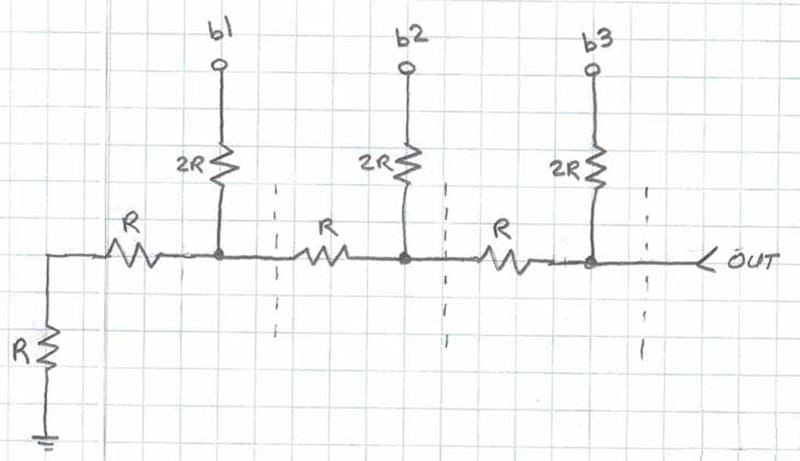 |
Figure 3: First Thevenin Equivalent
You may notice that this process repeats itself each time we work from left to right, successively replacing combinations of resistors with their equivalents. As you can see in Figure 4, the circuit ultimately simplifies to a single resistor R.
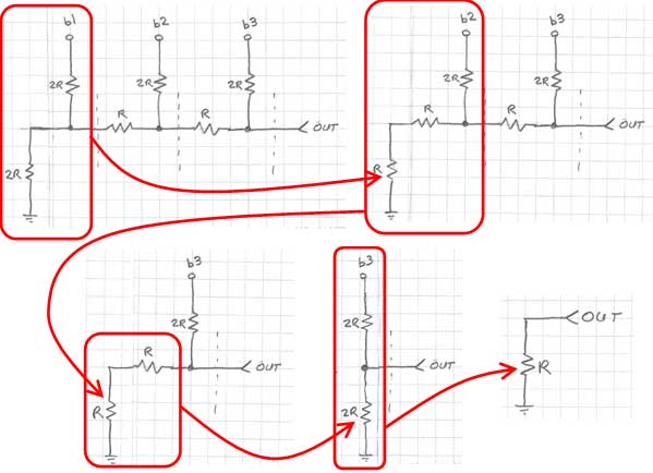 |
Figure 4: Calculating the equivalent output resistance of the R-2R network
Thus, the output impedance of the R-2R resistor network is always equal to R, regardless of the size (number of bits) of the network. This simplifies the design of any filtering, amplification or additional analog signal conditioning circuitry that may follow the network. How to Calculate Analog Voltage Output
Next, we’ll look at how to calculate the analog voltage output for a given parallel digital input on the b0, b1, etc. inputs. We’ll use the same Thevenin equivalents technique shown above, as well as Superposition. Superposition tells us that if you individually compute the contribution of a given source to the output (with all others voltage sources shorted and current sources opened), you can then sum the results for each of the sources to obtain the final result for the output.
We’ll calculate the contribution of two of the bits of our 4-bit R-2R DAC in Figure 5 to show the process. We’ll assume the bits b0 and b2 are logic high, and bits b1 and b3 are logic low (ground).
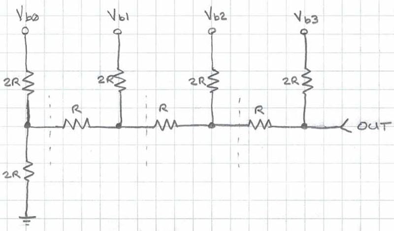 |
Figure 5: 4-bit R-2R example
We start by replacing the circuit to the left of the left-most cut-line with its Thevenin equivalent. Figure 6 shows the Thevenin equivalent, which is the series resistor of value R (parallel combination of two 2R resistors), and the open circuit voltage from the resistor divider (Vb0/2).
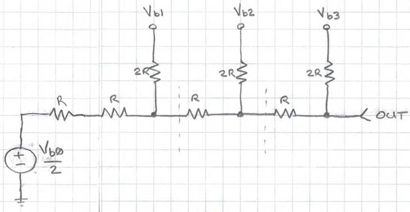 |
Figure 6: Replacing the first stage with its Thevenin equivalent
The process continues methodically, step by step for each cut-line, substituting the equivalent circuit for each stage, as shown graphically in Figure 7.
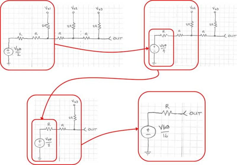 |
Figure 7: Calculating the contribution of Vb0 to the output
We can see that the voltage contribution from bit b0 is 1/16th of the logic high voltage level. Each bit stage that this voltage passes through cuts the contribution by a factor of 2. You may begin to see a theme here…
Next, we’ll compute the contribution from bit b2, as shown in Figure 8 below:
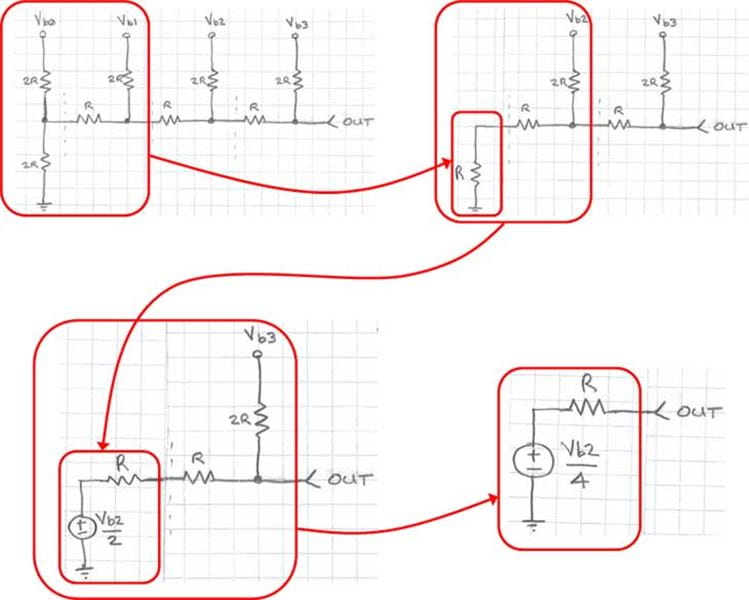 |
Figure 8: Computing the contribution of bit b2 to the output
From the Thevenin equivalent analysis shown earlier, we know that we can replace any portion of this circuit to the left of any of the cut lines with a resistor of value R, shown as the first step in Figure 8. Next, we follow the same Thevenin equivalent process to the output. As you may have already suspected, the contribution of bit b2 is simply Vb24. Thus, the analog output voltage when bits b0 and b2 are equal to logic one is simply given by Vb016 + Vb2/4.
In a more general sense, the contribution of each bit to the output is a simple binary weighting function of each bit. As you work back from the MSB to the LSB, the voltage contribution each bit is cut in half. Thus, the general form of the equation to calculate the output voltage is shown in Figure 9.
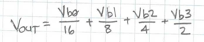 |
Figure 9: Formula to calculate output of 4-bit R-2R DAC
The R-2R resistor ladder based digital-to-analog converter (DAC) is a simple, effective, accurate and inexpensive way to create analog voltages from digital values. Monolithic R-2R resistor networks are available from various resistor component manufacturers, making it easy to incorporate them into your designs.
Range of output
The given solution above is unipolar: output will be between 0V and the output in formula 9.
If you want bipolar output you need either to B0..Bx to be able to be +-output. Or shift level in a summationsamp.
Some links:
From the last link two nice figures
 |
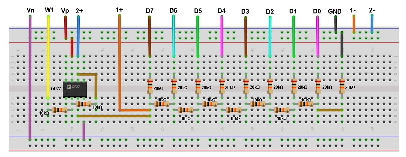 |
Use 10kOhm (R) and 20kOHm(2R) They will give you a low current load on the digital pins. Many digital pins have a builtin current limitation for one pin AND for the sum of output of digial pins.
Simple vero board mockup for a 8 bit R2R DAC. Use 20kOhm for 2R and 10kOhm for R values /Jens
|
|
Unaccurate resistor values
Common pop-corn resistors are normally with 1% tolerance. This means it can have a values which differs up to 1% from the nominal value:
Ex: 1000 Ohm 1% resistor - interval [990 - 1010] Ohm
So the output from the MSb bit can vary +- 1%
So how many bit resolution is worthwhile ? well - it does not real make sense to have bits that add less that the unaccuracy on the MSB bit.
bit weights in output:
1 bit  LSB      1/2   eg 1 bit DAC and so forth
2 bit  LSB      1/4
3 bit  LSB      1/8
4 bit  LSB     1/16
5 bit  LSB     1/32
6 bit  LSB     1/64
7 bit  LSB    1/128   eg 7 bit DAC (and approx 1% tolerances)
8 bit  LSB    1/256
9 bit  LSB    1/512
10 bit LSB   1/1024   eg 10 DAC (and approx 0.1% tolerances)
11 bit LSB   1/2048
12 bit LSB   1/4096
...
So a according to fig 9
Vcc multiplied with …
- 1 bit output  0  ,  1/2
- 2 bit output  0  ,  1/4  ,  1/2  ,  (1/2 + 1/4)
- 3 bit output  0  ,  1/8  ,  1/4  ,  (1/8 + 1/4)  ,  1/2  , (1/8 + 1/2)  ,  (1/4 + 1/2)  ,  (1/8 + 1/4 + 1/2)

just binary counting :-)

distance between values

- 1 bit 1/2   0.5
- 2 bit 1/4   0.25
- 3 bit 1/8   0.15
- 4 bit 1/16  0.0625
- ...
- 7 bit 1/128 0.0078125


Max value
- 1 bit   1 -   1/2   0,500
- 2 bit   1 -   1/4   0,750
- 3 bit   1 -   1/8   0.875
- 4 bit   1 -  1/16   0.9375
- ...
- 7 bit   1 - 1/128   0.9921875
...


all above multiplied with digital pin voltage on the R2R network (5,0, 3,3,.. V)
So you see 1 bit is crappy and it slowly becomes better
So for 1% resistors it looks like a 7 bit R2R DAC is enough.
If you have 0.1% resistors you can go for a 10 bit DAC
happy hacking
Jens
Note: R2R is patented in US pat US6150971A
Did expire 2019-06-22 - not many years ago
see here for patent
(tak til PLL for link)
As long as you retain this notice you can do whatever you want with this stuff on these pages.
If we meet some day, and you think this stuff is worth it, you can buy me a beer in return :-)
(C) Jens Dalsgaard Nielsen
credit for license this goes to phk@FreeBSD.ORG
