mma73x1l - a 3-axis analogue accelerometer
Measures acceleration in three dimensions (x,y,z) .
Below is a small sample with x axis measurement attached to analog port A1 on an Arduino.
(The accelerometer is supplied with 3.3V from the Arduino)
void setup() {}

int x-acc;
void loop()
{
	x-acc = analogRead(A1);
	Serial.println(x-acc); // NB this is a number in range 0-1023 eq to 0-5V.
	delay(500);
}
So basicly you have to measures the voltages and convert it to an acceleration.
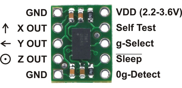 |
mma7361L A three axis accelerometer on a breakout board |
Datasheet
The three variants(mma7341L 7341LC and 7361L) are in principle the same except for different ranges (from 1.5g to 11g)
They are all plugin compatible to the cansat shields
mma7341LC.pdf data sheet (+-3g, +-9g)
mma7341L.pdf data sheet (+-3g, +-11g)
mma7361L.pdf data sheet (+-1.5g, +-6g)
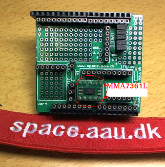 |
mma7361L on AAU cansat shield v4 |
Operations
The three analog outputs for Xacc, Yacc and Zacc are connected to analog A1, A2 and A3:
Xacc -> A1
Yacc -> A2
Zacc -> A3
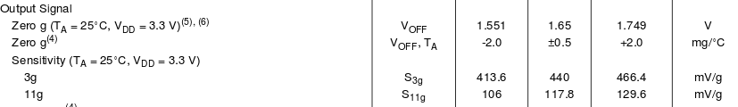
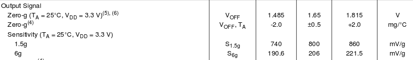
Below you can see voltage output for mma73x1.
Please note there is three numbers for each value: For mma7341LC 0g is 1.65V. But due to component variations it can be in have any value between 1.551V and 1.749V.
So you have to do calibration.
The values are stable and will normally not changes during operations.
 |
Output for mma7341L |
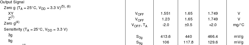 |
Output for mma7341LC |
 |
Output for mma7361L |
Range selection
The mma73x1 boards can be set in low and high range mode by the g-select pin.
In default mode(g-select pin low) it is in low range (like +- 1.5g or 3g)
The g-select pin shall be pulled high for high range.
On the AAU cansat shield v4 the g-select pin is connected to digital pin D6.
Example code for setting mma73x1 in high range mode:
void setup()
{
	pinMode(6,OUTPUT);     // configure as digital output
	digitalWrite(6,HIGH);  // and set it high
}
void loop()
{
}
A small example for mma7361L
We have the mma7361L and want to switch to high range: +-11g
We can from datasheet see:
0g is equal to
A very small example
void setup()
{
	Serial.begin(9600);
	pinMode(6,OUTPUT);
	digitalWrite(6,HIGH); // in 11 g range
}

int Xvalue;
float XaccV, XaccG;
void loop()
{
	Xvalue = analogRead(A1);
	XaccV = 5.0*Xvalue/1023.0; // convert reading to volt
	XaccV = Xacc - 1.65;       // voltage offset to 0g (See datasheet above)
	XaccG = XaccV / 0.1178;    // and datasheet states 0.1178V pr g
	Serial.println(XaccG);
	delay(1000);

	// NB NB no calibration carried out
}
Calibration
It is quite simple to do a calibration.
We will use earth gravity and measure 0g, -1g and 1g just by turning the sensor ( I think you can figure out how…).
So there are three positions equals -1g, og and 1g - datz all.
We will use the program below to measure all three axis and print measurements out in Volt.
You can let it run for some time and do some averaging in a spreasheet or modify the progra, to do so.
void setup()
{
	Serial.begin(9600);
	pinMode(6,OUTPUT);
	digitalWrite(6,HIGH); // in 11 g range
}

int value;
float XaccV, YccV, ZaccV;
void loop()
{
	value = analogRead(A1);
	XaccV = 5.0*value/1023.0; // convert reading to volt

 	value = analogRead(A2);
	YaccV = 5.0*value/1023.0; // convert reading to volt

 	value = analogRead(A3);
	ZaccV = 5.0*value/1023.0; // convert reading to volt

 	Serial.print(XaccV); Serial.print(" ");
 	Serial.print(YaccV); Serial.print(" ");
 	Serial.println(ZaccV);
	delay(100);

	// for reading out raw values for calculating calibration
}
Some hints for calibration:
 |
The three positions for x axis accelerometer |
So you will see three voltages
XaccHigh the highest equals 1g
XaccMid the in middle equals 0g
XaccLow the lowest equals -1g
So …
Use XaccMid to subtract from reading (was 1.56V in example above)
USe (XaccHigh-XaccLow)/2.0 as sensitivity (was 0.1178V in example above)
That is all
YOU HAVE TO DO IT FOR ALL THREE AXES BQ THERE MIGHT NOT BE EQUAL.
You can of course to 100 measurement and find average for a more accurate value, but I think it is not nescessary
Two movies (in danish)
Basicly they show how to measure acceleration with an arduino.