Aliasing and sampling
Aliasing is a phenomenia which comes to live when you are sampling an analog signal to slow. This will disturb your digitized analog signal.
The Nyquist Shannon theorem states that you must sample with more the twice the highest frequency in the signal to void aliasing.
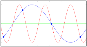
The phenoma can be viewed on figure below. Red dot indicates sampling and by trying to reconstruct the sampled signal a red curve connects the sample points. But the orgiginal blue signal do not look like the orginal blus analog signal.
Something is wrong
 |
The problem
The basic problem is that we are sampling to slow.
Nyquist-Shannons sampling theorem states that Fs (sampling frequency) must be above 2* Fsignal-max.
So if maximum frequency in the signal to be sampled is 100 Hz sampling mst be carried out with more than 200 Hz.
See https://www.youtube.com/watch?v=Jv5FU8oUWEY for a more in depth explanation.
Three other links for in depth explanation
https://www.analog.com/media/en/training-seminars/tutorials/MT-002.pdf
https://www.youtube.com/watch?v=yWqrx08UeUs&list=RDQMHQuaF46nOjE to be viewed
Conclusion 1 - sampling rate
Given highest frequency in the signal is Fs we shall with a frequency higher than 2 * Fs
https://en.wikipedia.org/wiki/Nyquist\\-Shannon_sampling_theorem the theory behind
Theory sets a lower limit at 2 * Fmax. But to be able to handle small remains of high frequency in the signal sampling with at least 4 times stipulated max signal frequency is normally choosen.
Take this as a engineering approach just 2 b sure
As shown in the menu above we cant reconstruct signal if we do not obey to this rule https://en.wikipedia.org/wiki/Nyquist\-Shannon_sampling_theorem
Problem solving location
So high frequencies must be removed before we sample the signal with an ADC - at analog level
So what we need is an analog anti aliasing filter in front of the ADC
Ideally it should be like
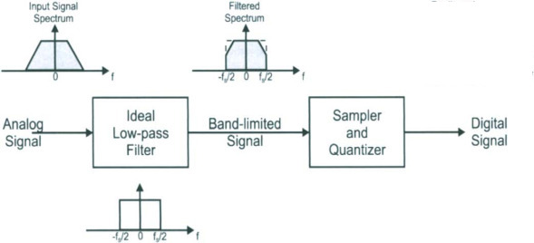 |
As the figure above indicate the lowpass filter (the antialiasing filter) should/should be of very high order - but this is in most /many cases unrealistic.
We need a implementable solution:
From https://www.sciencedirect.com/topics/computer-science/butterworth-filter:
A Butterworth filter is defined as a maximally flat filter that provides the sharpest roll-off possible without inducing peaking in the Bode plot. It is commonly used in control systems due to its lack of peaking.
Butterworth filters are often used allthough there exist a range of very high filters. Those are not the scope here.
Butterworth filter
A Butterworth filter is describes as:
The Butterworth filter is a type of signal processing filter
designed to have a frequency response that is as flat as possible in the passband.
It is also referred to as a maximally flat magnitude filter
wikipedia
Some things to consider
To be used as anti aliasing filter we have to select a comprimise of
cutoff frequency
must at least be less than the half of the samplings frequency (Nyquist-Shannon criteria)
Prefer to be at max half or on third of samplings frequency (Jens rule)
Order of filter
Order of antialiasing filter
Increasing order of filter increase the slope or rate of damping as seen in figure below
first order filter is no often seen as antialiasing filter.
second or third order(or even higher) are preferred
As order goes up phase shift goes up as well (which also can be seen as delaying)
Order of filter - the figure below
About the figure - can be used for simple scaling to other frequencies for discussing and design.
The figure is normalised to 1 rad/sec in cut off frequency,
x axis logaritmic
y axis in dB ( so log(signal/nom signal)
at cut off frequency all WB filters has 3 dB damping = 0.707 down in signal
| first order | 6 dB /octave | 20 dB/decade |
| second order | 12 dB /octave | 40 dB/decade |
| third order | 18 dB /octave | 60 dB/decade |
| fourth order | 24 dB /octave | 80 dB/decade |
Steepness is orderOfFilter * 20dB/decade or 6 dB/octave
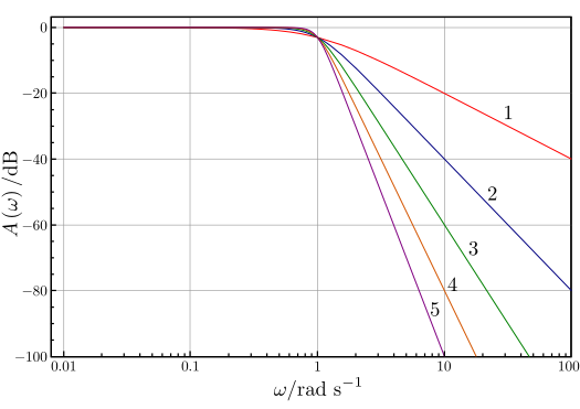 |
An example From the figure
Fs (samplings freq) == 4 rad/sec
Anti aliasing filter cutt off freq is set to 1 rad/sec
At max alowable frequency ( 2 [rad/sec]) (Nyquist freq) one octave
At 2 times the cut off frequency(2 rad/sec) (one octave above) the signal is roughly reduced to
1,2,3,4,5 order - in dB 6,12,18,24,30 dB or 0.5, 0.25, 0.13, 0.06, 0.003
At 10 times the cut off frequency(10 rad/sec) (one decade above) the signal is roughly reduced to
1,2,3,4,5 order - in dB 20,40,60,80,100 or 0.10, 0.01, 0.001, 0.0001
Please note 10 rad/sec is 2.5 times sampling frequency - this is just for illustarting purpoes
My more or less subjective selections criteria
Look at sensor signal on an oscilloscope
is noise present ?
If possible use the scope too see a frequency plot for the sensor signal
you should be able to see dominant noise frequencies
decide for sampling frequency, cut off frequency and order for anti aliasing filter
Out of scope here - adc resolution
We should use an anti aliasing filter
But consider the following
If you are using a high resolution adc (12,13,14,15,16,… bit) noise might reduce your real resolution on the sampled signal.
14 bit equals 2^14 or 16384 step (16 bit 65536)
So given 14 bit with max level at 1V a single bit represent 1/16384 mV or 0.6 mV.
So is average noise is at 0.6mV or even higher you will loose at least 1 bit of out the 14 bit.
Implemention of BW lowpass filter to be used for anti aliasing
We are now dealing with analog electronics.
In the links below there are suifficent mth to calculator BW filters, so no need to repeat it here.
-
it is explained a design methology to calculate order of your bw filter based on how much damping you need.
use the table below to find the appropriate second order filters which then must be set in series.
Butterworth as second and first order blocks
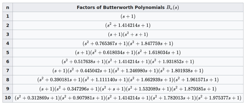 |
An example normalized to cut off freq is 1 [rad/sec]
A third order consists of - acc to table - of two blocks in series
first order filter omega/(s+1)
second block (omega * omega)/(s*s + s + 1)
For implementation of Sallen-Key lowpass filter see
Analog considerations
See the figure below
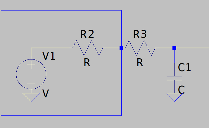 |
If R2 are around same size as R3 then cutoff frequency for the filter is dependent of R2+R3 and not R3 alone.
omega_0 = 1/(R3*C1)
changes to
omega_0 = 1/((R2+R3)*C1) on fig below
You can either for for R2 << R3 or as in the figure below insert a voltage follower buffer which has a very high input impedance.
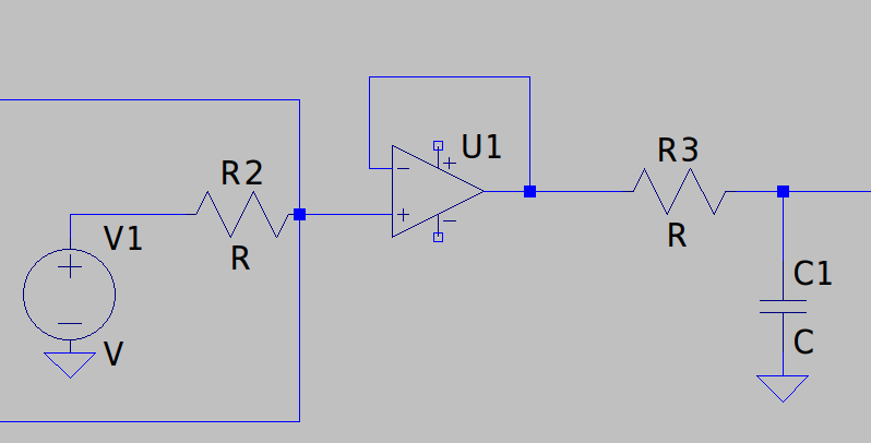 |
Its our of scope for to design it but should be fairly simple
FILMS
Illustrative movie https://www.youtube.com/watch?v=ACWa_mMhSJs
EOP
parking lot for links
As long as you retain this notice you can do whatever you want with this stuff on these pages.
If we meet some day, and you think this stuff is worth it, you can buy me a beer in return :-)
(C) Jens Dalsgaard Nielsen
credit for license this goes to phk@FreeBSD.ORG
